Supplies
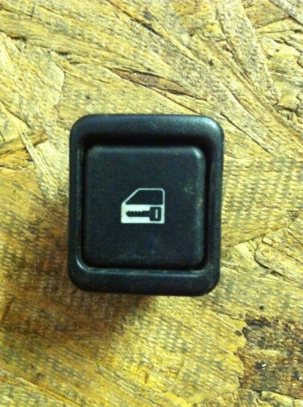
Lock Button [61318368931]
Lock button frame [51168201451]
Connector [61138380696]
Wire and pin [61130005197]
Flat headed Screw Driver
Drill and Drill Bit
File
Pen
Quick splices or connectors
Lock button frame [51168201451]
Connector [61138380696]
Wire and pin [61130005197]
Flat headed Screw Driver
Drill and Drill Bit
File
Pen
Quick splices or connectors
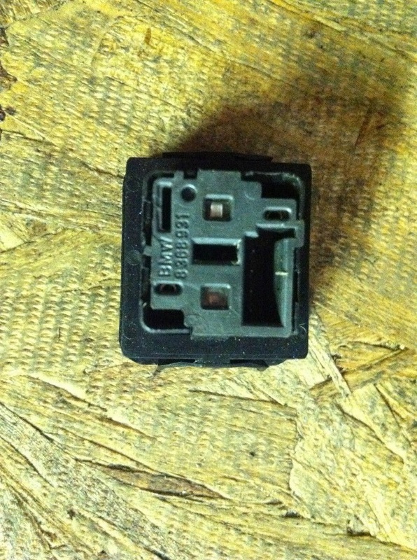
The Button Explained
The Wire Loom will have 4 wires in it. Color designations are for organization purposes.
Pin 1 [Green]= Wire to Lock Pin on Alarm Harness
Pin 2 [Blue]= Wire to Illuminated Wire of Window Switch
Pin 3 [Black]= Wire to Ground of Window Switch
Pin 4 [Red]= Wire to Constant Hot Pin on Alarm Harness
Pin 1 and 4 go to the Black Harness for a factory Alarm System. [more detail later]
Pin 2 and 3 tap into the Window switch for illumination [more on this later]
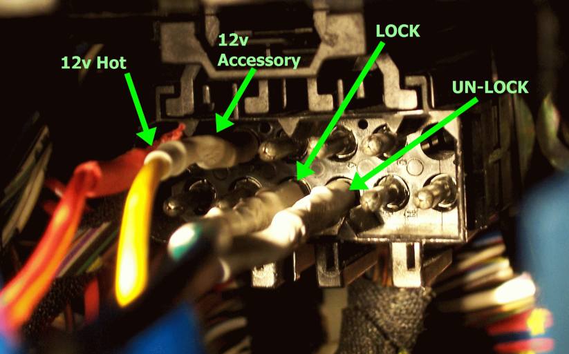
The Black Alarm Port
This is a 12 Pin Alarm Port found behind the Glove box. This is what we will use to make the doors lock. There are 2 rows and 6 columns.
+-----------------------------+
1 2 3 4 5 6
7 8 9 10 11 12
+-----------------------------+
Top:
1. 12v Hot [all times] use for pin 4 on lock button
2. 12V Switched ignition
3. Ground
4. Passenger door sensor [Negative trigger]
5. Driver door sensor [Negative trigger]
6. Empty
Bottom:
7. Siren
8. Hazards [Negative trigger]
9. Lock [12v trigger] use for pin 1 on lock button
10. Unlock [12v trigger]
11. Trunk Sensor [Negative trigger]
12. Dome light
+-----------------------------+
1 2 3 4 5 6
7 8 9 10 11 12
+-----------------------------+
Top:
1. 12v Hot [all times] use for pin 4 on lock button
2. 12V Switched ignition
3. Ground
4. Passenger door sensor [Negative trigger]
5. Driver door sensor [Negative trigger]
6. Empty
Bottom:
7. Siren
8. Hazards [Negative trigger]
9. Lock [12v trigger] use for pin 1 on lock button
10. Unlock [12v trigger]
11. Trunk Sensor [Negative trigger]
12. Dome light
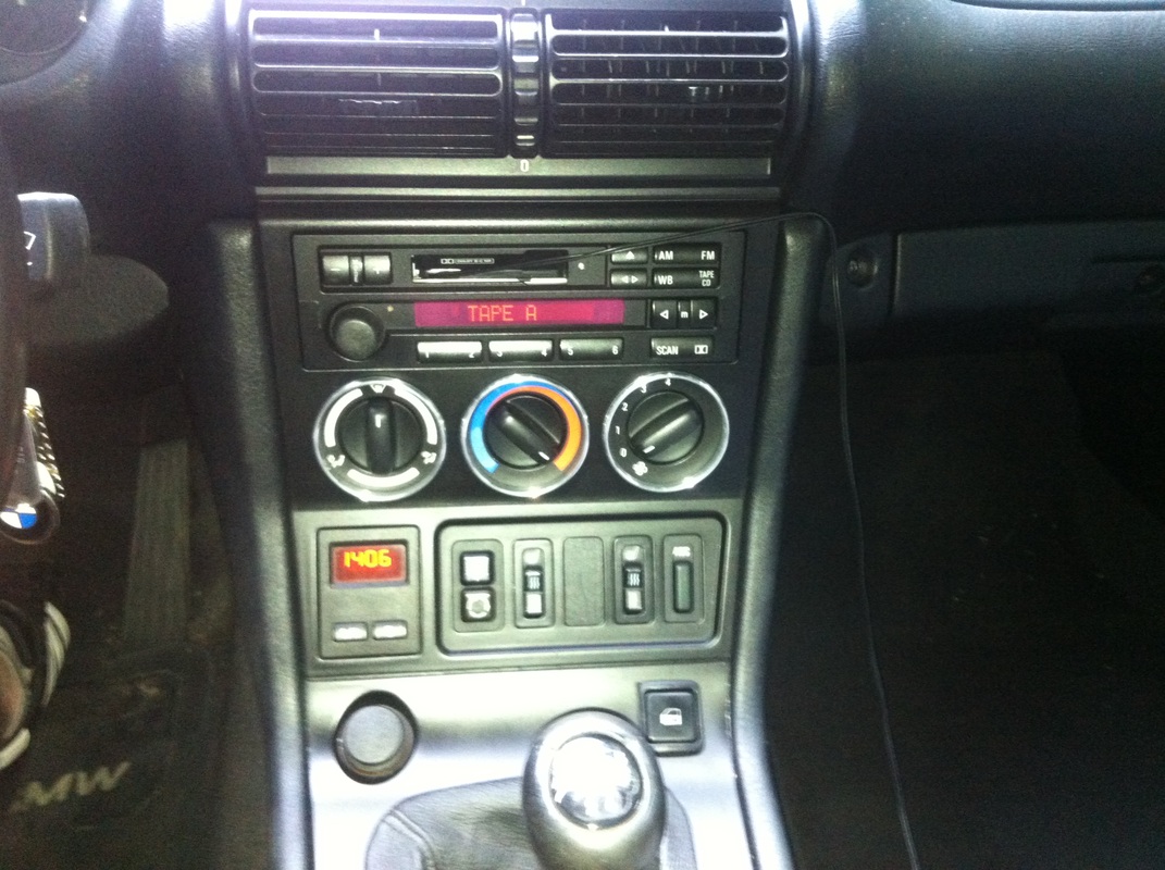
Window Button for illumination
This is how you will illuminate the lock button.
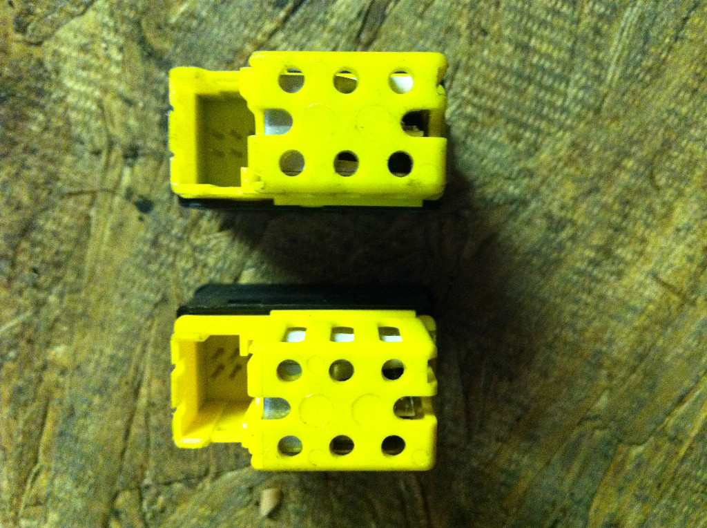
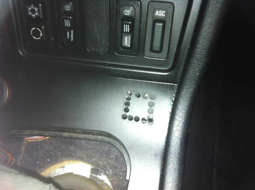
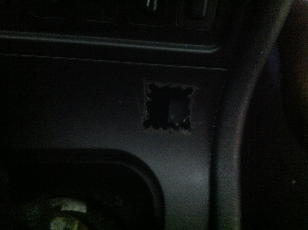
Installing the Button
Drill multiple small holes into your console, then use a pair of cutters to remove the middle and file everything until the button frame fits.